This is a high-level technical summary about everything (mostly) related to how the USB bus powers the peripheral devices connected to it. We wrote it at first for internal reference, but then noticed it could be of help to our readers. Enjoy!
USB in brief
At the time of this writing (september 2015), there are 4 remarkable versions of the USB standard:
- USB 1.x
- USB 2.0
- USB 3.0/3.1
- USB-C
The USB standard is asymetric:
- The master is called host and uses a type-A connector.
- The slave is called device (peripheral) and uses a type-B connector.
As an exception to the previous, the On-The-Go (OTG) extension allows a device with type-B connector (which should take the slave role) to behave under certain circumstances as a host (master).
A USB host can implement one or more host controllers:
- Each host controller implements a root hub with typically several type-A USB ports.
- Each host controller can manage up to 127 devices connected in a star/tree hierarchy of up to 5 levels. The hubs, which create the branches of the hierarchy, also count towards the 127 maximum number of allowed devices.
Each device can implement one or more functions simultaneously, for instance:
- A serial communications channel (CDC - Communication Device Class).
- A keyboard, mouse or joystick HID (Human Interface Device)...
Each evolving version of the standard has increased the maximum binary rate of the raw low-level communications and the complexity of the protocol:
- Enumeration and negotiation.
- Exchange of information types: isochronous, interruption based and bulk transfers.
- Negotiation of the maximum power (electrical current) consumption allowed for the peripheral.
I won't delve here into the details of the protocol, information exchange types and device addressing.
| Version | Features | Notes and extensions |
| USB 1.1 (Aug 1998) | Low Speed (1.5 Mbps) Full Speed (12 Mbps) |
Connectors type-A and type-B. |
| USB 2.0 (Apr 2000) | High Speed (480 Mbps) | - Connectors mini-A and mini-B (Oct 2000). - On-The-Go (Dec 2006), allows two devices with type-B connectors to communicate, one of them acting as a host. - Battery Charging 1.1 Specification (Mar 2007, Apr 2009), allows a power supply unit and hosts acting as battery chargers. Up to 100 mA without negotiation (allowing the so-called "dead battery" use case). Up to 1.8A with negotiation. - Micro-USB Cables and Connectors Specification 1.01 (Apr 2007). - Battery Charging Specification 1.2 (Dec 2010), allows up to 1.5A without negotiation. Allows high speed simultaneous communication while charging/powering a device. |
| USB 3.0 (Nov 2008) USB 3.1 (Jul 2013) |
SuperSpeed (5 Gbps) SuperSpeed+ (10 Gbps) |
The connector is usually blue. Backwards compatible with USB 2.0 cables and devices. - USB Type-C Specification 1.0 (Dec 2014), defines a new connector, type-C, smaller than the previous ones and reversible (non polarized), which will gradually replace all previous connector and cable types. Extensible (future-proof), supports the encapsulation of other non-USB protocols (alternate mode). Power baseline increased to 900 mA. Negotiated power currents of 1.5A and 3.0A. |
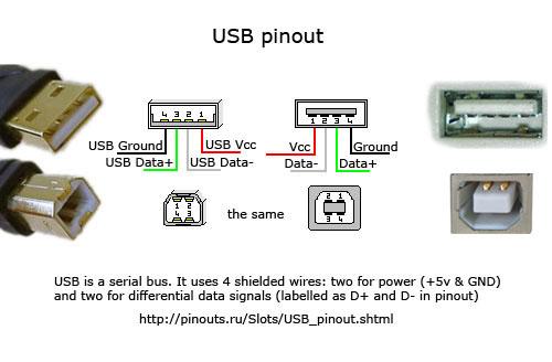
Pinout detail of connectors type-A and type-B female (receptacle, jack, socket) and male (plug).
Variants of USB connectors type-A and type-B.
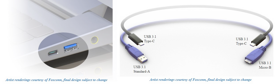
New USB type-C cable and connectors.
Electrical power
As a general rule,
- Female type-A connectors deliver energy (current).
- Female type-B connectors consume energy (current).
Exceptions:
- On-The-Go mode, where the device which temporarily assumes the host role will power the other device, to which it will communicate.
- New type-C cables and connectors.
USB 1.x and 2.0 specify a voltage supply of 5V ± 5% (4.75–5.25V) between the positive and ground terminals of the bus (VBUS). However:
- USB 3.0 relaxes the voltage supply to 4.45–5.25V, lowering the minimum allowed voltage.
USB 1.x and 2.0 require that the peripheral device identifies itself as Low/Full Speed,
- The electronics of the device must have an internal power supply rail of 3.3V,
- The logic of D+ and D- signals is 3.3V.
- The device can have other power rails internally, for instance: 5V, 2.5V, 1.8V...
- The communication signal is encoded differentially (NRZI) between terminals D+ and D-.
- A Full Speed device must have a pull-up resistor connected from D+ to 3.3V.
- A Low Speed device must have a pull-up resistor connected from D- to 3.3V.
- The differential signalling for High Speed communications is of low amplitude (400mV).
Maximum power consumption/current management
So, how much power can consume a peripheral device?
In USB 1.x/2.0,
- Inmediately after it is connected, a device can consume up to 100mA.
- Then, it may negotiate a maximum consumption of 500mA.
In USB 3.x,
- Inmediately after it is connected, a device can consume up to 150mA.
- Then, it may negotiate a maximum consumption of 900mA.
- With the new type-C connectors a device is allowed to negotiate power consumptions up to 1.5A and 3.0A.
A charge port is a special type of USB port which can be present in a power supply adapter or a host and which can deliver between 500mA and 1.5A without negotiation. Beware, however, the charge supply voltage,
- For currents up to 500mA, it is guaranteed a voltage of 5V.
- For currents between 500mA and 1.5A, the charge port is allowed to supply a voltage as low as 3.6V. This is because this types of ports are designed for charging Lithium batteries, and 3.6V is considered enough for this purpose.
Other remarks:
- Non standard charge ports can deliver up to 2A, por example, as in the most of power supply adapters desined for tablet devices.
- The 1.5A current limitation is because this is the typical maximum current guaranteed by the manufacturer of a type-A USB 2.0 connectors.
- The typical maximum current guaranteed by the new type-C connectors is 3.0A.
The present/future of USB power delivery
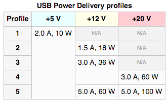
There is a not yet widely kwown specification from the USB Promoters Group (Jul 2012) which will allow to use these USB cables,
- Type-A to micro-B for power profiles 1-4 (10/36/60W maximum).
- Type-A to B for power profile 5 (60/100W maximum).
This way, hopefully, we will soon be able to power up our laptops with a specially manufactured cable with the marking PD (“Power Delivery”), which will certify which power profile is guaranteed for the cable by the manufacturer.
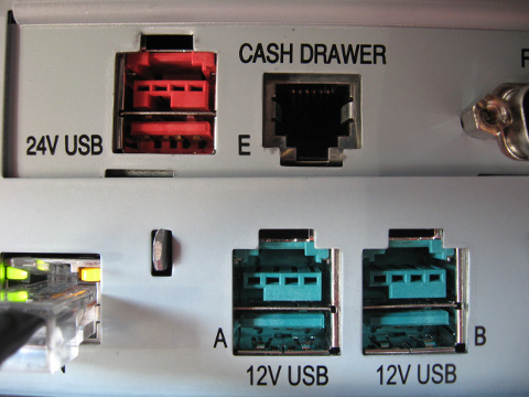
Apart from the above, there is a proprietary specification (patented) by IBM for Point of Sale (PoS) and similar equipments, called PoweredUSB.
In short, it uses two stacked connectors, one which is a standard USB 1.x/2.0 and a second one for the electrical power, as shown in the image below.
References
If you want to know more about the USB standards and internals of the protocol, before actually delving into the full specification, these are good references to start with:
- USB in a nutshell, by Beyond logic.
- USB Made Simple, a series of articles on USB.
Images
The images referenced in this post are solely owned by their respective rights holders:
- Pyramid representing a "USB host controller root hub and hierarchy of devices in tiers", EDN Network, article "USB Eases Data Acquisition".
- "Pinout detail of connectors type-A and type-B female (receptacle, jack, socket) and male (plug)", Pinouts.ru, page "USB pinout".
- "New USB type-C cable and connectors", artist renderings courtesy of Foxconn.
- Table of "USB Power Delivery profiles", Wikipedia, article "USB".
- Image of "PoweredUSB connectors", Wikipedia, CC BY 3.0.
Did you like this article? We'd love to receive your feedback. And if you don't want to miss new posts, subscribe to our mailing list.
Discuss