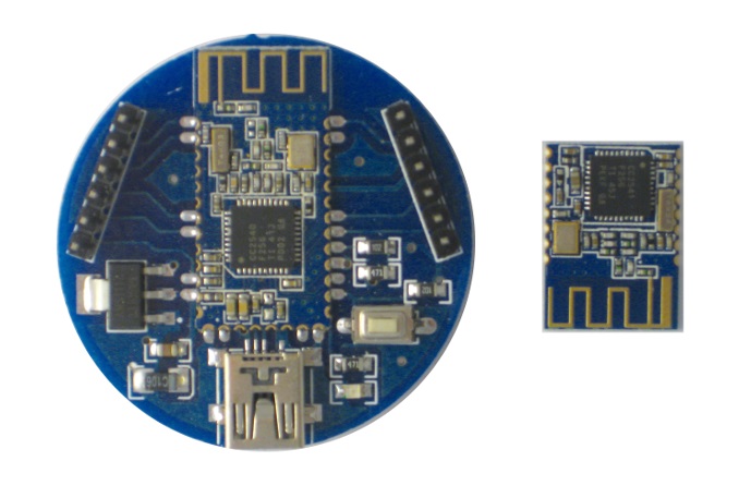
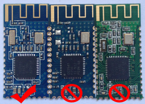
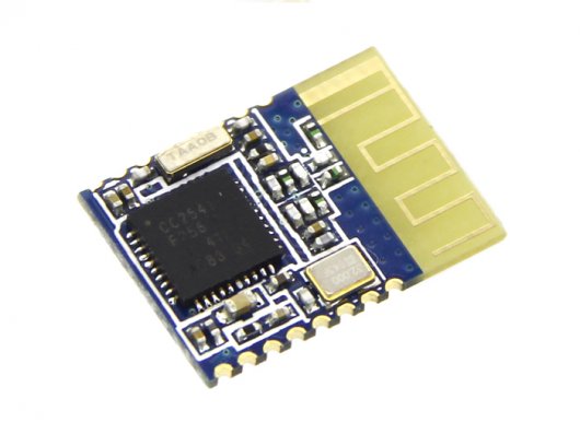
HM-10 is a Bluetooth Low Energy (BLE) module built on Texas Instruments CC2540 o CC2541. Chinese manufacturer Jinan Huamao Technology is the developer of the board and the firmware, although there are several clones available in the market as described in the original documentation.
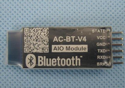
The module can also be purchased already mounted on a breakout board that exposes six male pins. This is the easiest form factor for a maker project since it does not require any soldering; we have easily connected it to an Arduino through jumper wires. Additionally, the HM-10 can also work autonomously without the need of a microcontroller (more on this in a future post)
HM-11 is a smaller form factor version of this module (HM-10) that exposes less pins from the original CC254x chip. Functionally they behave the same and all the information described in this post also applies to HM11.
Power
The basic HM-10 module (and the two TI chips it is based on) works at 3.3V so it cannot be directly connected to a 5V microcontroller (e.g. Arduino). However the HM-10 breakout boards integrate voltage (DC-DC) and logic level converters (LLC) so that their pins can be directly wired to an Arduino.
Standard Working Mode (Serial Connection Emulation)
The HM-10 abstracts and packs a Bluetooth Low Energy connection in a serial connection. The original out-of-the-box firmware of the module exposes a BLE peripheral with a proprietary connectivity service (Service UUID: 0000ffe0-0000-1000-8000-00805f9b34fb) that enables bidirectional communication between the module and any other central device that connects to it. The service defines a single characteristic (Characteristic UUID: 0000ffe1-0000-1000-8000-00805f9b34fb) that stores 20 bytes of unformatted data:
The HM-10 module implements a serial connection in pin 1 (TXD in breakout boards) and pin 2 (RXD) that is linked logically to the BLE service and connection. Any data that is received through the RXD pin is sent through notifications to the central device. Any data written by the central device is output through the TXD pin. This mechanism wraps the BLE connection as a standard serial connection for the connected microcontroller (Arduino, Raspberry Pi). For example, in the case of Arduino, this connection is controlled as any other serial connection using the Serial or SoftwareSerial library.
Sample Code
In this example we use an Arduino Uno and the console of the IDE to establish a communication between the computer/Arduino and an Android mobile app.
The Arduino sketch just connects the console serial port (Arduino pins 0 and 1) with the software serial port where we connect the BLE module (pins 7 and 8 in Arduino; pins TXD and RXD in HM-10 module).
Any data received by the HM-10 over BLE (from the mobile app) is passed to the Arduino Serial port and displayed on the IDE console. Similarly, any data input in the IDE console is passed through the software serial port to the HM-10 and is then transmitted over BLE to the Android app. If the HM10 is not connected to any central device (Android smartphone), the data input in the console is simply discarded.
#include <SoftwareSerial.h>

SoftwareSerial mySerial(7, 8); // RX, TX
// Connect HM10      Arduino Uno
//     Pin 1/TXD          Pin 7
//     Pin 2/RXD          Pin 8

void setup() {
  Serial.begin(9600);
  // If the baudrate of the HM-10 module has been updated,
  // you may need to change 9600 by another value
  // Once you have found the correct baudrate,
  // you can update it using AT+BAUDx command
  // e.g. AT+BAUD0 for 9600 bauds
  mySerial.begin(9600);
}

void loop() {
  char c;
  if (Serial.available()) {
    c = Serial.read();
    mySerial.print(c);
  }
  if (mySerial.available()) {
    c = mySerial.read();
    Serial.print(c);
  }
}
You can use MSMBLE Android app (available in Google Play) to test this example. It requires Android 4.4 and BLE support by the smartphone or tablet.
The app can scan the presence of BLE devices and discover their services and characteristics. In particular, it can connect to HM-10 modules and exchange data with them over BLE using the mechanism explained above. You can find the sourcecode ot his Android app in github
There are many other iPhone of Android apps that you can use to connect to HM-10 modules (e.g. Nordic)
HM-10 Configuration
The HM-10 module can be configured over the serial connection (pins RXD and TXD) using AT commands. Although the official documentation lists many commands, not all of them are supported by the version of the module that we have tested (v 540).
Note that the AT commands do not require Line Feed or Carriage Return codes (LF, CR). If you use the Arduino IDE console to send them , make sure that you select “No line ending”.
List of commands:
AT It just answers back OK and informs that the module is active and waiting for new commands AT+ADDR? It returns the MAC address of the HM-10 module AT+VERR? It returns the current firmware version AT+RENEW It resets the module to the original factory settings AT+RESET It resets/restarts the module AT+MODEx It changes the way the module processes AT commands:
AT+MODE0(default value): It only accepts AT commands over the serial connection (RXD/TXD) until a central device connects to the moduleAT+MODE2Same as MODE0 but once a connection is established, AT commands can be sent over BLE by the central device. This feature can be used to change remotely the value of a GPIO pin of the HM-10
AT+UUID0xnnnn It changes the short service UUID used by the HM-10 module to encapsulate the serial connection (the default value is 0xFFE0) AT+CHAR0xnnnn It changes the short characteristic UUID used by the HM-10 module to encapsulate the serial connection (the default value is 0xFFE1) AT+PIOxy (x: 2-B ; y: 0-1) It changes the state of GPIO pin x of the HM-10 module with value y (0 Off; 1 On) e.g. to set GPIO2 on, use AT+PIO21 This command can be used to control a relay from a central device (a smartphone) if the module is configured in Mode 2 (see command AT+MODE above) AT+BEFCxyz It defines the value/state of GPIO pins (2 to B) when the module is powered on (valid values:000 to 3FF). For example, to condigure GPIO2 just after power on, use AT+BEF200 AT+NAMExxxxxxxxx It changes the name of the module AT+ROLEx (x: 0-1; 0 - peripheral; 1 - central; default value 0) It defines the role of the HM-10 module. In the case that the module is configured as a central device, you can use commands AT+DISC?, AT+CON and AT+CONN to connect it to another peripheral device.
There are more commands that let you configure and control additional features and parameters of the HM-10 module. We recommend that you read the official documentation and play with them. Sometimes, there are commands that block/hang the serial connection. We are not sure why this happens. Just unpower the module and, when you repower it again, the module will work fine with the latest configuration.
In this post we have seen HM-10 working as peripheral device. In a future post we will see how to configure the module so that it can work as a central device or as an iBeacon.
If you liked this content, keep tuned and susbscribe to our blog to get notified when we post new content!
This post was first published in Spanish in the wiki of Makespace Madrid. If you can read Spanish, do browse through the site. You will find lots of useful information related to BLE and other topics.